
- /
- /
Getting Started Guide: MSRTK Module
Overview
This guide is intended for first time Multi-Sensor RTK module (MSRTK) users and provides an overview of how to handle with the required software, connect to and configure the MSRTK module, and acquire position and attitude solutions.
By the end of this guide, you will be able to acquire a fixed RTK solution using ANavS® MSRTK modules. The steps in this guide should take you about half an hour and should be performed outdoors.
Content
- Powering your MSRTK Module
- Connections of your MSRTK Module
- Setup your MSRTK Module for RTK- and Attitude Determination
- The ANavS®-Wizard to configure the MSRTK Module
Powering your MSRTK Module
The Multi-Sensor RTK module (MSRTK) has three different options for power supply.
Important: All options should deliver minimum current supply of 2A.
The first option for power supply is via Powerbank (see Figure 1).
For this option please use the delivered Powerbank (Capacity: 10000mAh) and the USB cable with Typ-C connector at one end.

Fig. 1: Power supply per Powerbank
The second option for power supply is via standard 230V AC Power plug (see Figure 2).
For this option please use the delivered Power adapter and the USB cable with Typ-C connector at one end.

Fig. 2: Power-Supply with AC Power Plug
The third option for power supply is via wires (see Figure 3).
For this option please take care of the polarity(+/-) and the voltage-range of 9V – 16V.

Fig. 3: DC Power-Supply per Wires
Connections of your MSRTK Module
The following section describes the different standard connectors and interfaces of the MSRTK module.
Figure 4 shows the antenna-connections with up to 3 GNSS antennas.
Important: Please connect for a One-Antenna setup to GNSS 1, for Two-Antenna setup to GNSS 1+2 and for a Three-Antenna setup to GNSS 1+2+3.

Fig. 4: GNSS Antenna connections
Figure 5 shows the standard connectors of the casing:
- SMA Connectors for GNSS: As already described in Figure 4, on the left side of the board are the connectors for the GNSS antennas. Please take care to connect in the appropriate order (GNSS 1, GNSS 2, GNSS 3).
- SMA Connector for LTE/Mobile Network: Please connect the delivered LTE Antenna if you want to use the integrated LTE-Chip for internet-access (for example to receive correction data from your RTCM Base Station).
- USB-Typ C for Power-Supply: As already described to use the Power-Plug or Powerbank for power supply.
- Camera Interface 1/2: The interfaces for ANavS® visual odometry sensor (VIS). Camera 1 can for example be used for the forward movement direction and Camera 2 for backward movement direction.
- USB-Interface: The standard USB interface can be used for example for data-storage, wifi-dongle, LTE-dongle, data-transmission, etc.
- Ethernet: The ethernet-port can be used for internet/network-connections to stream for example the ANavS sensor fusion solution.
- Power-Supply per Wires: As already described in Figure 3, one has the possibility to power the board with DC-voltage per wires.
Special interfaces like UART, CAN, FPGA for incremental-decoder and GPIOs are described in the Knowledge Base section “Developer Information” .

Fig. 5: Standard interfaces lead to the casing
Setup your MSRTK Module for RTK- and Attitude Determination
This chapter is intended to properly setup the MSRTK board for the rover (car, roboter, UAV, etc). Figure 6 shows a typical setup:
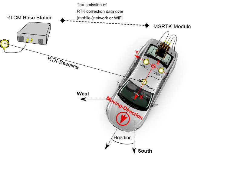 Fig. 6: MSRTK board setup at a car rover
With three GNSS-antennas on top of the car/rover the software can calculate the yaw, pitch and roll angle of the rover. Furthermore you need a RTCM Base Station for streaming RTK correction data. The RTK correction data is typically streamed from an ANavS® RTCM Base Station or from an external service-provider with internet-connection or WiFi. The RTK-Baseline defines the centimeter-accurate position of your rover.
Antenna Placement Guideline
This is a very important step of your setup and has a direct impact on the position- and attitude performance of the sensor fusion. The placement of the antennas defines the attitude-baseline (e.g. in figure 6 the baseline b12), that means the yaw, pitch and roll angle of your rover. Please mount the antennas in accordance of your use-case and carefully measure the distances between the antennas (measurement-error < 1 cm). The configuration of the sensor fusion with these measured distances is done in the ANavS® Wizard and is described in the section The ANavS® Wizard to configure the MSRTK Module.
Please pay attention to the following:
* The minimum distance between any two GNSS antennas is 30 cm.
* Please note that the attitude accuracy increases with the distance between the GNSS antennas (0.25° heading-accuracy per meter antenna spacing)
* Please align your antennas in the same way to minimize the impact of antenna phase center offsets. The high-grade antennas have an arrow marked on the rear side of the antenna. The orientation of the low-cost patch antennas is simply defined by the orientation of the cable-connector.
* Please consider and measure also a height-offset between the mounted GNSS antennas. We recommend a placement at the same height level for the beginning as this prevents any sign errors of the differential height and typically enables the best performance.
* For setups with three GNSS antennas (3D-Setup for yaw, pitch and roll angle determination), please make sure that distance measurements in perpendicular directions are really having a 90° angular spacing as otherwise the distance measurements do not fit to the actual geometry. This would prevent any reliable solution.
MSRTK Module Placement Guideline
The following figure 7 shows a placement example of the MSRTK module and GNSS antennas in the body-frame of your rover (top-view).

Fig. 7: MSRTK-module and GNSS antenna placement in body-frame
Please pay attention to the following:
* The movement direction of your rover is defining the orientation of the x-axis.
* The MSRTK module includes an IMU, which needs to be oriented in a certain manner: The MSRTK module must be oriented such that the SMA-connector of the LTE is pointing towards the movement direction.
* To get the best performance, it is good practice to mount the MSRTK module in the center of rotation of your rover.
The ANavS®-Wizard to configure the MSRTK Module
In the previous section, you became familiar with the hardware and its setup. This section describes the use of the ANavS® Wizard software. The ANavS® Wizard can be found in the installed folder-structure <Installation-Folder>/ANavS_RTK_Wizard. To be able to configure and receive data of the module, please connect with the WiFi Access-Point “ANAVS_MSRTK_AP” (Password: anavsrtk) of your powered-on MSRTK module. Please note that the boot time of the Linux-OS is approximately 1-2 min.
Figure 8 shows Step 1 of the ANavS® Wizard application:
Please select the first option “Starting ANavS Sensor Fusion on MSRTK module”.

Fig. 8: Select the desired Modus (1. Step)
Figures 9 and 10 show Step 2 of the ANavS® Wizard application:
In this step the Wizard is checking the communication between your Laptop/PC and the MSRTK module. If you get the shown error message in figure 9, please check again your WiFi connection.
Figure 10 shows the typical window when the WiFi connection is working. One can adjust the settings for the 4G module, the WiFi module and CAN (described in an extra article in the knowledge base).
Instructions for 4G-settings:
* To use the internal 4G-module, one can insert a micro-SIM card into the slot of the MSRTK module. However, ANavS delivers MSRTK modules with already equipped SIM-cards, which are provider-independent. The MSRTK module automatically selects the strongest network.
* The 4G antenna must be screwed on the right SMA-connector.
* If you are using your own SIM-card, please define all necessary informations for dial-in your SIM-card in the mobile-network of your service provider. Information for APN, Dial-UP Number, Username and Password of your service provider can be found in the web. For users of the ANavS SIM-card the APN is “em” and Dial-Up Number is “T*99#” (Username and Password is not neccessary).
* Click the button “SEND CONFIG” to send the information to the MSRTK module.
* In the next step, click “(RE-)START 4G” button. If all provided information for the SIM-card are correct and LTE-reception is available at your position, the field “4G Is Inactive” becomes “4G is Active” and the color turns from red to green.
* The configuration is saved to enable an automatic re-connection with the mobile-network after each reboot.
Instructions for WiFi-Settings:
The WiFi-module is delivered with two different modis.
* Access-Point (AP): The standard way is the Access-Point (AP) functionality. This means that the MSRTK module sets up its own WiFi-network with the SSID “ANAVS_MSRTK_AP” with password “anavsrtk”. Please use this mode for your first steps to get familiar with the system.
* Connect to an existing network: Additionally, one can toggle to the functionality where the MSRTK module connects to an existing WiFi-network. To give the information to the MSRTK module, please use the input-boxes for SSID and PASSWORD with the buttons “ADD WLAN-Setting” or “REMOVE WLAN-SETTING”. It is possible to define a lot of known WiFi-networks. But take care, you must know the assigned IP-address of your MSRTK module in your network to be able to communicate with the ANavS® Wizard to the MSRTK module. The new IP must be signed in the message box by clicking on the “Settings”-button in the lower left corner. A detailed description of how to find the IP-address of your MSRTK module is included in the article Using the IP scanning-tool NMAP. The article Broadcasting RTCM-Data for MSRTK Modules explains how to connect per WiFi to the RTCM Base Station.

Fig. 9: WiFi error message (2. Step)

Fig. 10: 4G/WiFi/CAN Settings of MSRTK module (2. Step)
Instructions for Ethernet-Settings:
With default settings, the ethernet port is waiting to get an IP address of a dhcp server (like a router). After connecting router with MSRTK module you can identify the MSRTK module via the dashboard of your router or scanning the network as explained in the article Using the IP scanning-tool NMAP.
Another option is to set a static IP for the MSRTK module and directly connect it with another device or laptop (please conatct support@anavs.com for this option).
Figure 11 shows Step 3 of the ANavS® Wizard application:
Now you have to define the number of used GNSS antennas mounted on the rover respectively screwed on the MSRTK module.
The impact of your selection:
1-Dimensional:
The attitude is estimated with movement and coupled with the IMU-gyroscope (one GNSS antenna connected). With this setup, you need some rover dynamic (curves, circles) to get an accurate attitude information of your rover.
2-Dimensional:
The attitude (yaw and pitch angle) is already determined without movement using fixed carrier-phase GNSS measurements and coupled with the IMU-gyroscopes (two GNSS antennas connected).
3-Dimensional:
The attitude (yaw, pitch and roll angles) is already determined without movement using carrier-phase GNSS measurements and coupled with the IMU-gyroscopes (three GNSS antennas connected).

Fig. 11: Select Attitude-Dimensionality (3. Step)
Figure 12 shows Step 4 of the ANavS® Wizard application:
The next step proves the GNSS antenna connection and if the count of founded GNSS antennas match with the previous selected Attiutde dimensionality (Step. 3). You only can go further if it matches in a proper way.

Fig. 12: GNSS antenna connections of MSRTK module (4. Step)
Figure 13 shows Step 5 of the ANavS® Wizard application:
The following figure shows the placement input of your GNSS antennas in the body-frame of your rover (top-view). Only when everything has been defined correctly, the user can proceed to the next steps (the right arrow on the top right part of the window appears).
Please pay attention on the following:
* The x-direction shown in this figure defines the movement-direction of your rover
* Please measure the distances as accurate as possible. The measurement-error should be below 1 cm
* Defining the z-Axis corresponds to the right-hand-rule. The thumb shows in movement-direction
* For setups with three GNSS Antennas, please use a right angle measurement-tool
* With the Auto-Set button the last configuration is reloaded

Fig. 13: Dimensions of GNSS antennas in body-frame of rover (5. Step)
Figure 14 shows Step 6 of the ANavS® Wizard application:
In Step 6, for streaming correction data of an (ANavS-)RTCM Base Station in the appropriate RTCM3.X-format, one has to define the correct input-stream. A hint for the suitable input-format notation is given in the Wizard-Window. To facilitate the user input, the last three streams are cached in a selectable history.

Fig. 14: Define RTCM Base Station input stream (6. Step)
Figure 15 shows Step 7 of the ANavS® Wizard application:
The ANavS® sensor fusion is customizable with some specific a priori information.
* For using a priori information about the reference station, an input-option is given here. One has to fill the dimension in the NED (North-East-Down)-Frame format to use this mask. Additionally, the accuracy of the measurement has to be set and needs to be activated with the appropriate button. Use this possibility only if the information is really exactly known and you are introduced in the NED-frame and how you can set this parameter in a correct manner. It’s not recommended for new User.
* The additional setting “Up-Velocity” is for constraining the velocity mainly in the horizontal plane. One can activate this options for applications like automotive or robotics. Please deactivate this option for UAV-applications or something similiar.
* The additional setting “Heading<>Velocity” is for constraining the velocity mainly to the heading direction. Again, one can activate this option for applications like automotive or robotics but not for UAV-applications.

Fig. 15: Settings for a priori information (7. Step)
Figure 16 shows Step 8 of the ANavS® Wizard application:
In the last step of the Wizard, the user can start the ANavS® sensor fusion with the green start-button. But before you start, please check further settings:
* The option “Save solution file” activates saving the realtime sensor fusion solution in a file. The format of the file depends on the selected type of solution output. Furthermore one gets a kml-file, which gives the user the opportunity to see the most interesting information (position, attitude, velocity, and acceleration) in a Google-Earth plot. The files are saved in <User-Path>/Documents/AnavsWizardAppData/output_data
* The option “Save raw-data” activates saving all processed sensor-data (GNSS, IMU, Barometer, Odometry, Visual-Odometry, …) with highly accurate timestamps to use it for postprocessing. The files are saved in <User-Path>/Documents/AnavsWizardAppData/output_data
* The option “Activate fast RTK-Fixing” is a fast-mode for RTK-Fixing. But keep in mind that the reliability of RTK-fixing can suffer with this option
* The option “Enable Autostart of RTK-Service” effects an automated start of sensor fusion after booting-up the MSRTK module with the last configuration. Your setting is transmitted to the MSRTK module after Start- and Stopping the sensor fusion software with the ANavS® Wizard. To see the solution in the GUI, execute the program ANavS_GUI.exe in the folder <Installtion-Path>/ANavS_Wizard/bin
* The option “Enable Attitude-Calibration” is only for experts with appropriate support-level. If this option is activated, no sensor fusion is running, but a distance measurement for the GNSS antennas mounted on the rover. This procedure helps to evaluate the correct measurement of GNSS antenna distances but needs expertise to interpret the solutions correctly
* The option “Type of Solution-Output” is explained in the Developer-Information articles ANavS® Binary Solution Output Format and NMEA Solution Output Format
* The option “Define Output-Port” defines the TCP-Port on which one can stream the sensor fusion solution (like the GUI). The default-value is 6001.
* The option “Customer-Code” is only for experts with appropriate support-level. The default-value is 0.
* The option “Output-Rate” is selectable wiht Low (5Hz), Medium(55-65Hz), and High(105-125Hz). The exact rate depends on the used sensors.

Fig. 16: Starting ANavS sensor fusion software on MSRTK module
After pushing the green start-button for triggering the ANavS® sensor fusion on the MSRTK module, the ANavS® GUI (figure 17) pops-up and the sensor fusion starts to run. The ANavS® GUI visualizes all sensor fusion estimates per graphs and on a map.
The map in the ANavS® GUI shows different stages of solution estimates:
* SPP-Solution (red): This solution is very inaccurate and a standard car-navi or smartphone solution
* RTK-Solution (green): This is the highly precise sensor fusion solution with centimeter accuracy. A tight coupling with other sensors (IMU, Odometry, …) is performed.

Fig. 17: ANavS® GUI with it’s cascaded solution-levels
Hints for ANavS® GUI handling and some Information:
* Left-Mouse clicking in the Google-Earth plot zooms-in
* Right-Mouse clicking in the Google-Earth plot zooms-out
* The Google-Earth map is only visible with scale-level 5 meter or higher
* In the Tab “Settings”, one can define the IP-address to which the GUI should connect
* The “Data rate” shows the amount of solution output data streamed to your Laptop/PC
* The “Relative Position” shows the baseline-vector from RTCM Reference Station to your Rover
* The “Last corrections” in the left upper corner shows the time since last RTCM correction data was processed. The counter should always be under 10 seconds to get best RTK performance. If no second-counter appears but only “N/A”, there is no connection between MSRTK module and your RTCM base station.
Important to get best performance:
* Gray or red light for the attitude signals that the attitude-solution is not fixed with GNSS phase measurements (no highly accurate attitude information)
* Gray or red light for the RTK-position signals that the position-solution is not fixed with GNSS phase measurements (no highly accurate position information)
* Orange light for Attitude/RTK signals that the sensor fusion solution lost the fixed state and Filters perform in a float mode
* Green light for Attitude/RTK signal that the position and/or attitude is fixed with GNSS phase measurements and a highly accurate solution is available
* Please start movement only with float (orange signal) or fixed (green signal) mode